Icosahedral subdivision of geometry on a sphere
Published on
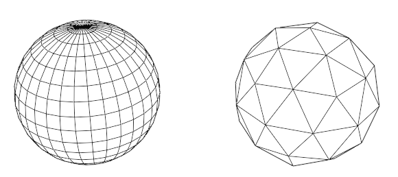
There exists no unique tessellation of a spherical surface into triangles, and all methods have different trade-offs. The most simple to implement procedural method for spherical surfaces, called UV spheres in 3D modeling software like Blender, splits the surface of the sphere in small rectangles divided by edges exactly as the lines of longitude and latitude on a map using the familiar Mercator projection. This is depicted on the left-hand side below.
An alternative that creates a vastly more uniform triangular tessellation is based on the subdivision of an icosahedron, and are often called icospheres. This is depicted on the right-hand side below. This method eliminates the problem of geometric pinching that UV spheres have, where increasing the resolution of the subdivision will accumulate many triangles that all end at the poles.
Goal
The goal is to implement an algorithm that efficiently subdivides geometry on a sphere based on an icosahedron. The input geometry is defined by the OpenGIS Simple Feature Access standards, and the code should output a 3D mesh with curved surfaces that are tessellated based on some number of subdivisions of an icosahedron.
High-level description of the algorithm
The algorithm consists of two parts, starting with projection:
- Every coordinate of a feature is projected on a face on the (non-subdivided) icosahedron.
- When connecting two coordinates, and the line between them crosses two or more different faces, we cut the line and add extra vertices on the edges between all the faces that are crossed.
- After all pairs of coordinates of a closed feature are handled as described above, we iterate over all faces touched by the previous step, and stitch together all broken line strings into closed rings by matching the cuts corresponding to lines entering and exiting the faces.
The second step subdivides every face of the icosahedron separately. We choose some level of resolution that corresponds to how much we subdivide in the vertical and horizontal directions.
- We split the face into vertical strips.
- We split each vertical strip into squares, by cutting in the horizontal direction.
- We split each square into two triangles by cutting once in the main diagonal direction.
- We again stitch together the geometry in each subdivided triangle as in the first part of the algorithm.
- Because polygons can contain holes, we use the orientation of the rings (clockwise or counterclockwise) to determine exterior rings and interior rings. We match interior rings to exterior rings by looking at the containment relation between them and use this to construct the polygons in each triangle.
Further processing is required in order to display the polygons, as we can only display triangles. This tessellation however falls outside the extend of this project, and we can simply use a 2D tessellation library like Lyon to do this for us.
Interactive demonstration
This interactive demonstration uses the Bevy engine to provide a cross-platform (web and native) interactive application. The version below is compiled to WebAssembly. The icosahedron is subdivided with a level of 10. Boundaries between administrative areas and edges between triangles are stroked in black, and every tessellated triangle has its own color.
Controls: drag to orbit the camera, and scroll to zoom.
Known issues
- Some edge cases in the input data are not handled properly in the implementation, but these deficiencies are not inherent to the algorithm. The main example of this would be that coordinates cannot be projected on the edge, or a vertex on the icosahedron.
- Some parts of the code that determines where the cuts are placed might be numerically unstable in some cases, this needs to be investigated more thoroughly.
- The generated mesh contains strictly too many vertices, as it does not do deduplication on the edges between the triangles.